
Difference Between Raster Scan and Random Scan in Tabular Form
Contents
Raster scan and Random Scan are the technique used to display the picture of an object on the screen of the desktop/pc monitor. The Key Difference between Raster Scan and Random Scan, In Raster Scan electron beam, is swept across the screen, one row at a time, from top to bottom. Random Scan electron beam is directed only to the parts of the screen where a picture is to be drawn.
Comparison Chart
| Raster Scan | Random Scan |
|---|---|
| The electron beam is swept across the screen, one row at a time, from top to bottom. | The electron beam is directed only to the parts of screen where a picture is to be drawn. |
| Its resolution is poor because raster system in contrast produces zigzag lines that are plotted as discrete point sets. | Its resolution is good because this system produces smooth lines drawings because CRT beam directly follows the line path. |
| Picture definition is stored as a set of intensity values for all screen points, called pixels in a refresh buffer area. | Picture definition is stored as a set of line drawing instructions in a display file. |
| The capability of this system to store intensity values for pixel makes it well suited for the realistic display of scenes contain shadow and color pattern. | These systems are designed for line- drawing and can’t display realistic shaded scenes. |
| Screen points/pixels are used to draw an image. | Mathematical functions are used to draw an image. |
| Cost is less. | Cost is more. |
| Raster display has ability to display areas,filled with solid colors or patterns. | Vector display only draws lines and characters. |
| Refreshing on Raster scan display is carryout at the Rate of 60 to 80 frames per seconds. | Refreshing in Random scan display to draw all the components of lines of pictures 30 to 60 frames per second. |
| It is used for photos.That is Why photoshop is Raster editing program. | It is used for text ,logs,letterheads. |
| Raster Scan Mainly in photos like JPG,PNG,GIF File Format | Random Scan system High Quality Images In SVG,the Size is Rescaleable like Logo in sites |
Raster Scan
- The architecture of Raster display. It consists of a display controller, CPU, video controller, refreshes buffer, keyboard, mouse, and CRT.
- The display image is stored in the form of 1’s and 0’s in the refresh buffer.
- The video controller reads this refresh buffer and produces the actual image on screen.
- It will scan one line at a time from top to bottom & then back to the top.

- In this method the horizontal and vertical deflection signals are generated to move the beam all over the screen in a pattern shown in Image.
- Here beam is swept back & forth from left to the right.
- When beam is moved from left to right it is ON.
- When beam is moved from right to left it is OFF and process of moving beam from right to left after completion of row is known as Horizontal Retrace.
- When beam is reach at the bottom of the screen. It is made OFF and rapidly retraced back to the top left to start again and process of moving back to top is known as Vertical Retrace.
- The screen image is maintained by repeatedly scanning the same image. This process is known as Refreshing of Screen.
- In raster scan displays a special area of memory is dedicated to graphics This memory is called Frame Buffer.
- Frame buffer holds set of intensity values for all the screen points
- That intensity is retrieved from frame buffer and display on screen one row at a time.
- Each screen point referred as pixel or Pel (Picture Element).
- Each pixel can be specified by its row and column Numbers.
Random Scan
- Random scan also is known as a vector display.
- Random scan display directly traces out only the desired lines on CRT.
- If we want line between point p1 & p2 then we directly drive the beam deflection circuitry which focus beam directly from point p1 to p2
- If we do not want to display line from p1 to p2 and just move then we can blank the beam as we move it.
- To move the beam across the CRT, the information about both magnitude and direction is required. This information is generated with the help of vector graphics generator.

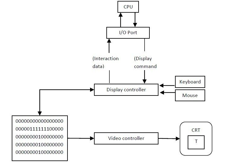
- Architecture of a vector display
- Image shows the architecture of vector display. It consists of display controller, CPU, display buffer memory and CRT.
- Display controller is connected as an I/O peripheral to the CPU.
- Display buffer stores computer produced display list or display program.
- The Program contains point & line plotting commands with end point co-ordinates as well as character plotting commands.
- Display controller interprets command and sends digital and point co-ordinates to a vector generator.
- Vector generator then converts the digital co-ordinate value to analog voltages for beam deflection circuits that displace an electron beam which points on the CRT’s screen.
- In this technique beam is deflected from end point to end point hence this techniques is also called random scan.
- We know as beam strikes phosphors coated screen it emits light but that light decays after few milliseconds and therefore it is necessary to repeat through the display list to refresh the screen at least 30 times per second to avoid flicker.
- As display buffer is used to store display list and used to refreshing, it is also called refresh buffer.
More Difference